



JLR Defender Adaptive Cruise Control Retrofit
OEM-Spec Radar-Guided Cruise Control for Defender L663 (2020–Present)
Adaptive Cruise Control Engineered for the Defender Platform
The Land Rover Defender L663 Adaptive Cruise Control retrofit is a professionally engineered system that enables radar-based adaptive speed regulation on Defender models not originally equipped with this feature. This system was designed from the ground up to integrate with the Defender’s unique electrical architecture, which is built upon the JLR Electrical Vehicle Architecture (EVA) platform featuring zonal electronic control.
Adaptive Cruise Control replaces the standard cruise control function by incorporating a 77 GHz forward-facing radar sensor that continuously monitors the traffic environment ahead of the vehicle. The system automatically adjusts throttle position, transmission gear selection, and brake application to maintain a safe and consistent following distance behind the vehicle detected in the driving path.
Technical Components & Integration Details
The Defender ACC retrofit kit includes the following components, each manufactured or sourced to meet JLR engineering specifications:
- 77 GHz Radar Sensor Module: A compact, weather-sealed radar unit installed within the front bumper assembly on the dedicated mounting platform. The sensor provides object detection at distances up to 200 meters with a ±8° horizontal field of view.
- Front Bumper Modification Kit: For Defender models not originally fitted with the radar-compatible bumper, a precision-machined aperture cover and mounting bracket are supplied to maintain the vehicle’s exterior aesthetic while enabling radar signal transmission.
- CAN Bus Wiring Harness: A dedicated wiring loom routed from the radar sensor to the central gateway module (CGM), connecting to the high-speed CAN bus for real-time data exchange with the ECM, TCM, ABS, and Instrument Cluster.
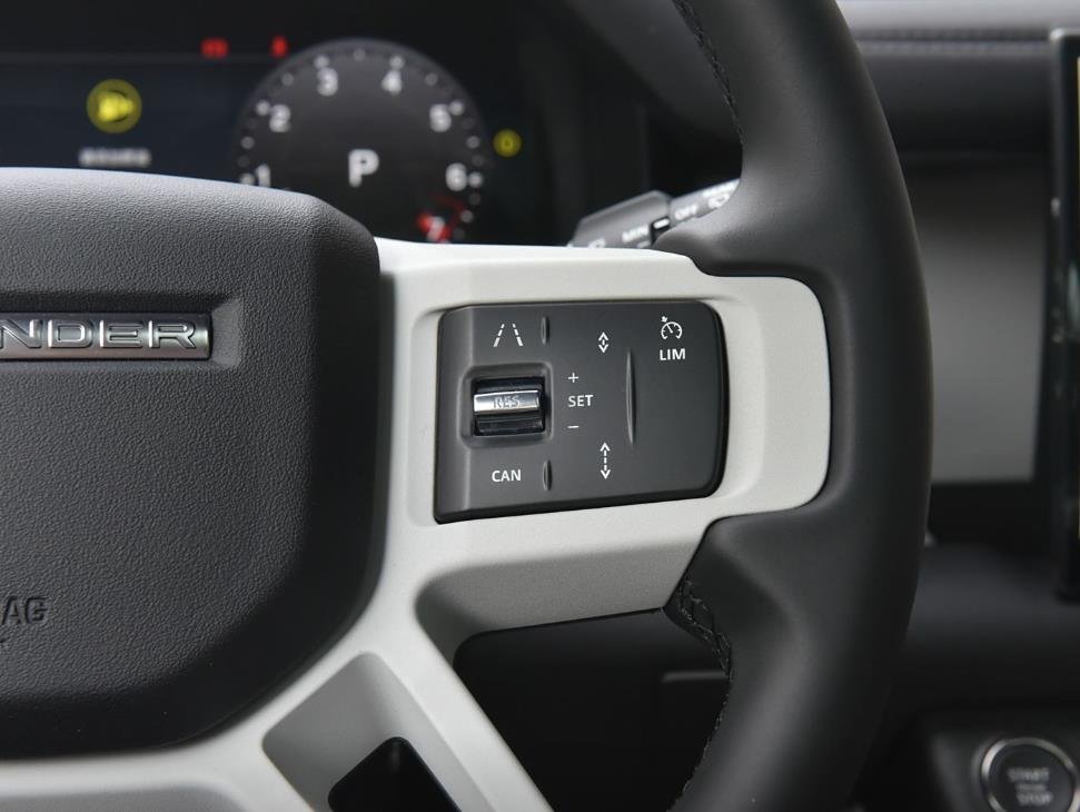
- Steering Wheel Switchpack: Replacement or reconfigured steering wheel controls with dedicated ACC buttons for SET+, SET−, RES (resume), GAP distance adjustment, and CANCEL functions.
- Instrument Cluster Reconfiguration: Software-level update to the Instrument Cluster firmware to display ACC status indicators, adaptive gap distance visualization, and system diagnostic alerts.
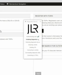
- CCF Programming via Pathfinder: The Defender’s Car Configuration File is updated using JLR Pathfinder diagnostic software to activate the ACC subsystem and register the radar module within the vehicle’s electronic topology.
Defender-Specific Engineering Considerations
The Land Rover Defender presents unique engineering requirements that distinguish this ACC retrofit from similar installations on other JLR platforms. The Defender’s body-on-frame construction, elevated ride height, and off-road-oriented suspension geometry require specific radar alignment parameters to ensure accurate object detection across varying load conditions.
Additionally, the Defender’s front-end design, particularly on models fitted with the steel bumper and recovery points, may require supplementary bumper modification to accommodate the radar sensor’s transmission window. Our installation team assesses each vehicle individually to determine the optimal mounting position, ensuring that the radar signal path is unobstructed by bull bars, winch installations, or auxiliary lighting.
The system is also calibrated to account for the Defender’s variable ride height when fitted with electronic air suspension (EAS). The radar module’s vertical alignment is referenced to the vehicle’s dynamic ride height data received via the CAN bus, ensuring consistent performance whether the vehicle is at standard ride height, off-road height, or access height.
Installation Procedure
The Defender ACC retrofit installation follows a structured protocol:
- Vehicle Assessment: Full diagnostic scan with JLR Pathfinder to verify ECU versions, CCF parameters, and existing wiring infrastructure.
- Radar Module Installation: The 77 GHz radar sensor is mounted on the dedicated bracket, aligned to the vehicle centerline, and secured to torque specification.
- Bumper Modification (if required): The radar-transparent aperture is cut into the bumper fascia using CNC-guided templates, and the sensor cover is installed.
- Wiring Harness Installation: The dedicated CAN bus harness is routed from the front bumper to the CGM, secured with OEM-spec cable management hardware.
- CCF Update & Calibration: Pathfinder is used to enable ACC in the CCF, register the radar module, and perform the automated radar alignment routine.
- Road Test & Validation: A comprehensive road test verifies speed regulation accuracy, gap-distance maintenance, stop-and-go functionality, and instrument cluster display correctness.
Related products


JLR Software

OEM Activations
OEM Activations

OEM Activations
Custom Coding Services DISCOVERY SPORT 2015-2019 Chip Tuning
JLR Software